Model Key-Point Identification
The Model Key-Point Identification tool can be found in the Flags to Apply section of the  Automatic Point Cloud Analysis tool.
![]() This tool requires Global Mapper Pro.
This tool requires Global Mapper Pro.
The Model Key-Point Identification tool allows for finding and applying a flag to points which are required for TIN (Triangulated Irregular Network) generation. First, a TIN is created using points from within the input layers, thinned based on the shared resolution parameter, as vertices. Next, similar TIN faces based on angle are combined until the number of faces is a fraction of the initial count based on the Reduction Level parameter. The points at the vertices of the remaining faces are then applied the Key-Point flag.
Parameters
Resolution
Use the shared resolution parameter found at the top of the Automatic Point Cloud Analysis dialog to determine the local neighborhood size used for the initial thinning and TIN generation.
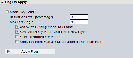
Reduction Level (percentage)
Specify the percentage of model TIN faces to be collapsed in the key-point identification process. The actual applied reduction factor may be lower then the value specified, in order to preserve the original topology. After the initial TIN is created connecting all points from the input layer, TIN faces will be combined until the specified reduction level is reached in terms of the total number of TIN faces.
Max Face Angle
Specify the maximum allowed angle for collapse of adjacent model TIN faces. This will determine a threshold of similarity in terms of angle TIN faces will need to have in order to be combined.
Overwrite Existing Model Key-Points
Reset any existing model key-point flags in the input point clouds prior to processing.
Save Model Key-Points and TIN to New Layers
Check this option to create two new output layers; one containing the identified Model Key-Points, and the other containing the Vector TIN created during the process.
Select Identified Key-Points
After performing the Model Key-Point identification, selecting this option will select all flagged points with the digitizer.
Apply Key-Point Flag as Classification Rather Than Flag
Set ASPRS Model Key-Point (Mass-Point) instead of applying a Key-Point flag to the output points. This will set the class code to 8, as defined by the ASPRS.
The Lidar Draw Mode Color by Key Point Flag can be used to visualize the flagged points.