The Layer Menu contains options for data creation or editing using the selected layers in the Overlay Control Center. Many of these options were previous found in the Overlay Control Center right click context menu, and are still available in the Overlay Control Center right click context menu under the Layer sub-menu.
These functions will apply to selected layers, so it is necessary to select the appropriate layers in the Overlay Control Center first.
- Create Workspace File from Selected Layer(s)
- SAVE - Save Changes Over Original File Data
- Export Layer(s) to New File
- Add Selected Layer(s) to Map Catalog
- Save List of Layers to Text File...
- Set Background Color for Layer in Control Center
- Calculate/ Copy Attribute Value(s)... Attribute Calculator
- Join Attribute Table/ File to Layer
- Split Into Separate Layers Based on Attribute Value
- Create Label Layer...
- Select Lidar Classes
- SAVE - Save Changes Over Original File Data
- Spatially Thin Lidar Point Clouds to Desired Spacing...
- Find and Delete Duplicate Lidar Points...
- Create Layer Coverage Box/ Polygon Area Features
- Create Area Features from Equal Values
- Vectorize Raster
- Create Point Features at Elevation Grid Cell Centers
- Find Extreme (Min/Max) Elevation Values
- Close Gaps Between Adjacent Features...
Create Workspace File from Selected Layer(s)
This option will generate a workspace just containing the selected layer(s) and their display options. This workspace can later be loaded with the File->Load Workspace menu command.
SAVE - Save Changes Over Original File Data
This option is available for modified lidar data. This will overwrite the original file to save the changes. This provides an option to preserve a workspace with modified lidar, without embedding all of the lidar modifications in the workspace file.

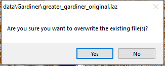
This tool will show a warning message before overwriting the original file. The file will preserve the original format.
It will also preserve the original and header information except those header values that have been modified, such as: Header Size, Offset to point data ,Point Data Record Length, Number of point records, Number of point by return, Min and Max Coordinate values, Start of Waveform Data Packet Record, Start of first Extended Variable Length Record.
With layers inside of a map catalog, the original lidar file that the catalog points to will be saved over.
Export Layer(s) to New File
This option will bring up a dialog to specify the export format. All selected layers in the Overlay Control Center that are compatible with the export format will be included.
Add Selected Layer(s) to Map Catalog
Adds the selected layer to an existing Map Catalog.See Add Selected Layers to Map Catalog for more information.
Save List of Layers to Text File
Exports a text file listing the layers currently loaded in the workspace. The layer descriptions as seen in the Control Center will be used in the resulting text file.
Set Background Color for Layer in Control Center
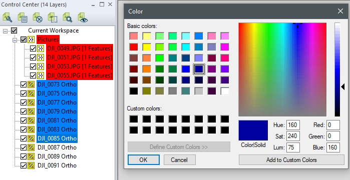
This option allows a background color to be added behind layer names or groups in the Control Center. After choosing the layer, layers, or group to change the background color of, a color picker box will open allowing the selection of a color. To reset the color that was chosen for a layer, simply reopen the Set Background Color for Layer in Control Center dialog via he Layer context menu, and change the color back to white.

Join Attribute Table/ File to Layer
This allows you to join a table of attribute values, either from a DBF file or from a text file, to the attribute table of a selected layer based on a common value of some attribute. You will be prompted to select the attribute from the attribute table file to join against a user-selected attribute from the selected layers. For text files, the first line must contain the attribute/ column names. Whenever a match is found, the other attributes from the data table are added to the matching record(s) in the file.
Split Into Separate Layers Based on Attribute Value
This option allows you to create new layers by splitting the selected layer(s) into new layers based on a particular attribute value or by the description, type, or name of each feature. The new layers will be grouped together using the name of the original layer unless the original layer was already in a group.
This causes new rectangular or polygonal coverage area features with the same name of the selected overlay (based on display label) to be created for each selected layer. When creating polygonal coverage areas a smoothing factor determines how tightly the coverage area matches the features in the layer. When selecting a smoothing factor, any value above zero is valid, larger values will create smoother areas while lower values will create rougher areas with the possibility of multiple areas being created.
This is useful for creating an image index as the filename of the layer will also be saved as an attribute of the area feature created from it.
Create Area Features from Equal Values
When a single raster or elevation grid layer is selected (with the exception of online sources), this option appears and allows you to create area features covering each distinct color or elevation value encountered in the raster file.
This causes a new layer to be created for each selected elevation grid layer with a spot elevation point feature at each grid cell center location. This provides a handy way to edit elevation layers as you can edit the elevation attribute of the created points or remove bad points, then create a new elevation grid from the layer.
Find Extreme (Min/Max) Elevation Values
This scans the selected elevation grid layers to find the minimum and maximum elevation values and reports both the values and their locations to the user. The complete list (up to 10,000 shared location) will be saved to a file, and a shorter list presented to the user. If enabled the check box to Create Point Features at Extreme Locations found below the reported minimum and maximum elevation locations will prompt the creation of a new layer in the workspace.
For streamed online layers, the data will be sampled at the default zoom level. For further detail in this analysis export the online terrain layer to a local file.
Note: The below options are only available in the Overlay Control Center right click context menu under the Layer sub-menu.
Sort Lidar Point Clouds by 2D location for Faster Display and Analysis
Reorder the points in the file organization so that they are ordered sequentially by location. This speeds up the display and processing of point cloud data.
Create 3D Areas from 3D Models...
This tool will convert a 3D model into 3D area features, assigned to the TIN Face Area feature type. For more information see Convert a 3D Model / Mesh
Create Image Layer from 3D Model(s)...
For 3D models that contain a texture, this tool will convert the applied texture into an orthoimage. For more information see Convert a 3D Model / Mesh
Create Point Cloud from 3D Model(s)...
This option will convert a 3D model into a point cloud by including the vertices, and sampling the faces. For more information see Convert a 3D Model / Mesh
Create Mesh Features from Terrain
This option will create an image draped (if specified) 3D model using the terrain layer and image layer. For more information see Convert a 3D Model / Mesh
Simplify TIN Layer...
This tool will create a new simplified TIN layer based on the specified Simplification Options. For more information on the available methods see Simplify Mesh.