STL
STL files are 3D model formats commonly used in CAD and 3D Printing applications. STL files describe only the surface geometry of a three dimensional object without any representation of color, texture or other common 3D Model attributes.
Import
For more information on loading STL files see Working with 3D Models. STL files typically use a Y-up orientation.
Export
The Export STL command allows the user to export any loaded elevation grid data sets to a standard STL format file.
To export loaded elevation data to an STL format, go to File > Export > Export 3D Format..., or right click on the layer in the Control Center and choose export from the Layer sub-menu.
There are 4 options for exporting STL files:
- Stereolithography STL Binary File (Vector Data Only)
- Stereolithography STL File (Vector Data Only)
- STL (3D Printing)
- STL (ASCII Text or Binary) File (Elevation Data Only)
STL (3D Printing)
This STL export option is designed to create small-scale 3D model outputs. This export method is focused on print dimensions and options necessary for a model used in 3D printing.

Model Output Dimensions
-
Choose the direct X and Y print dimensions or measurements for the data, ideally scaled to fit on the bed of a 3D printer. 3D print dimensions are typically scaled to millimeter, centimeters, or inches (specify the unit below).
-
Preserve Horizontal Aspect Ratio: Check this box to maintain the X and Y ratio to prevent horizontal distortion.
-
Units: Only applies to horizontal (X&Y) values.
-
Z Scalar: Vertical Exaggeration. Increase this value for more dramatic elevation changes equally across the dataset. The result is similar to the 3D viewer’s vertical exaggeration option.
Add base and walls extended below lowest elevation: Enable this option to generate a base and sidewalls for the model.
-
Base Thickness (mm): This determines how far below the lowest point in the data the base will be extruded to. Setting this to 0 will create the base at the lowest point. This may create a hole or thin area in your 3D print depending on layer thickness.
Add base to walls: Uncheck this box to only create walls with no base.
Resampling
- Nearest Neighbor - simply uses the value of the sample/pixel that a sample location is in. When resampling an image this can result in a stair-step effect, but will maintain exactly the original color values of the source image.
- Bilinear Interpolation - determines the value of a new pixel based on a weighted average of the 4 pixels in the nearest 2 x 2 neighborhood of the pixel in the original image. The averaging has an anti-aliasing effect and therefore produces relatively smooth edges with less stair-step effect.
- Bicubic Interpolation - a more sophisticated method that produces smoother edges than bilinear interpolation. Here, a new pixel is a bicubic function using 16 pixels in the nearest 4 x 4 neighborhood of the pixel in the original image. This is the method most commonly used by image editing software, printer drivers, and many digital cameras for resampling images.
- Box Average (2x2, 3x3, 4x4, 5x5, 6x6, 7x7, 8x8, and 9x9) - the box average methods simply find the average values of the nearest 4 (for 2x2), 9 (for 3x3), 16 (for 4x4), 25 (for 5x5), 49 (for 7x7), 64 (for 8x8), or 81 (for 9x9) ) pixels and use that as the value of the sample location. These methods are very good for resampling data at lower resolutions. The lower the resolution of your export is as compared to the original, the larger "box" size you should use.
- Filter/Noise/Median (2x2, 3x3, 4x4, 5x5, 6x6, 7x7, 8x8, and 9x9) - the Filter/Noise/Median methods simply find the median values of the nearest 4 (for 2x2), 9 (for 3x3), 16 (for 4x4), 25 (for 5x5), 49 (for 7x7), 64 (for 8x8), or 81 (for 9x9) pixels and use that as the value of the sample location. This resampling function is useful for noisy rasters, so outlier pixels do not contribute to the kernel value. Some common sources of raster noise are previous compression artifacts or irregularities of a scanned map/image.
- Box Maximum (2x2, 3x3, 4x4, 5x5, 6x6, 7x7, 8x8, and 9x9) - the box maximum methods simply find the maximum value of the nearest 4 (for 2x2), 9 (for 3x3), 16 (for 4x4), 25 (for 5x5), 49 (for 7x7), 64 (for 8x8), or 81 (for 9x9) pixels and use that as the value of the sample location. These methods are very good for resampling elevation data at lower resolutions so that the new terrain surface has the maximum elevation value rather than the average (good for terrain avoidance). The lower the resolution of the export file is as compared to the original, the larger "box" size that should be used.
- Box Minimum (2x2, 3x3, 4x4, 5x5, 6x6, 7x7, 8x8, and 9x9) - the box minimum methods simply find the minimum value of the nearest 4 (for 2x2), 9 (for 3x3), 16 (for 4x4), 25 (for 5x5), 49 (for 7x7), 64 (for 8x8), or 81 (for 9x9) pixels and use that as the value of the sample location. These methods are very good for resampling elevation data at lower resolutions so that the new terrain surface has the minimum elevation value rather than the average. The lower the resolution of the export file is as compared to the original, the larger "box" size that should be used.
- Gaussian Blur (3x3, 5x5, 7x7) - the Gaussian blur methods calculate the value to be displayed for each pixel based on the nearest 9 (for 3x3), 25 (for 5x5), or 49 (for 7x7) pixels. The calculated value uses the Gaussian formula that weights the values based on the distance to the reference pixel.
The Sample Spacing section allows the user to select the grid spacing to use when generating the file. The default value is the average of the grid spacings of all the currently loaded raster and elevation overlays.
If the Always Generate Square Pixels option is checked, the smaller of the specified x and y resolutions will be used for both the x and y resolution.
Selecting Always Generate Square Pixels ensures that the resultant image file will look good even in software that is not able to deal with pixels that aren't square.
To specify the spacing in units other than those of the currently selected view/ export projection, press the Click Here to Calculate Spacing in Other Units button.
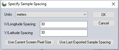
Specify the X and Y spacing of the output pixels in any of the selected units. These pixel dimensions will be translated into the units of the display projection during export. The Use Current Screen Pixel Size button will update the X and Y values to the dimensions of the map display. Use Last Exported Sample Spacing will update the X and Y values to the most recent export resolution.
Interpolate to Fill Small Gaps in Data
Any small areas with missing data will be filled in by interpolating the surrounding valid data. This is useful for filling small gaps between adjacent tiles or small holes in elevation data.
Export to a Z-up Orientation
STL files use Y for the vertical axis designation by convention (Y-Up orientation). Check this option to use Z for the vertical axis.
Export a Binary STL File (Much Smaller than Text STL)
The default export is an ASCII text readable STL format. Check this option to export the file as binary, which will reduce the file size.
Elevation Data Export
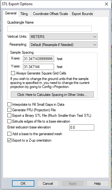
When selected, the STL (ASCII Text or Binary) File (Elevation Data Only) command displays the STL Export Options dialog which allows the user to setup the export. The dialog consists of a General options panel which allows the user to set up the grid spacing and vertical units, a Tiling Panel, a Coordinate Offset/Scale tab and an Export Bounds tab which allows the user to set up the portion of the loaded data they wish to export.
Elevation data may be exported from a raster grid format to other 3D model formats by first exporting to this STL option.
- Nearest Neighbor - simply uses the value of the sample/pixel that a sample location is in. When resampling an image this can result in a stair-step effect, but will maintain exactly the original color values of the source image.
- Bilinear Interpolation - determines the value of a new pixel based on a weighted average of the 4 pixels in the nearest 2 x 2 neighborhood of the pixel in the original image. The averaging has an anti-aliasing effect and therefore produces relatively smooth edges with less stair-step effect.
- Bicubic Interpolation - a more sophisticated method that produces smoother edges than bilinear interpolation. Here, a new pixel is a bicubic function using 16 pixels in the nearest 4 x 4 neighborhood of the pixel in the original image. This is the method most commonly used by image editing software, printer drivers, and many digital cameras for resampling images.
- Box Average (2x2, 3x3, 4x4, 5x5, 6x6, 7x7, 8x8, and 9x9) - the box average methods simply find the average values of the nearest 4 (for 2x2), 9 (for 3x3), 16 (for 4x4), 25 (for 5x5), 49 (for 7x7), 64 (for 8x8), or 81 (for 9x9) ) pixels and use that as the value of the sample location. These methods are very good for resampling data at lower resolutions. The lower the resolution of your export is as compared to the original, the larger "box" size you should use.
- Filter/Noise/Median (2x2, 3x3, 4x4, 5x5, 6x6, 7x7, 8x8, and 9x9) - the Filter/Noise/Median methods simply find the median values of the nearest 4 (for 2x2), 9 (for 3x3), 16 (for 4x4), 25 (for 5x5), 49 (for 7x7), 64 (for 8x8), or 81 (for 9x9) pixels and use that as the value of the sample location. This resampling function is useful for noisy rasters, so outlier pixels do not contribute to the kernel value. Some common sources of raster noise are previous compression artifacts or irregularities of a scanned map/image.
- Box Maximum (2x2, 3x3, 4x4, 5x5, 6x6, 7x7, 8x8, and 9x9) - the box maximum methods simply find the maximum value of the nearest 4 (for 2x2), 9 (for 3x3), 16 (for 4x4), 25 (for 5x5), 49 (for 7x7), 64 (for 8x8), or 81 (for 9x9) pixels and use that as the value of the sample location. These methods are very good for resampling elevation data at lower resolutions so that the new terrain surface has the maximum elevation value rather than the average (good for terrain avoidance). The lower the resolution of the export file is as compared to the original, the larger "box" size that should be used.
- Box Minimum (2x2, 3x3, 4x4, 5x5, 6x6, 7x7, 8x8, and 9x9) - the box minimum methods simply find the minimum value of the nearest 4 (for 2x2), 9 (for 3x3), 16 (for 4x4), 25 (for 5x5), 49 (for 7x7), 64 (for 8x8), or 81 (for 9x9) pixels and use that as the value of the sample location. These methods are very good for resampling elevation data at lower resolutions so that the new terrain surface has the minimum elevation value rather than the average. The lower the resolution of the export file is as compared to the original, the larger "box" size that should be used.
- Gaussian Blur (3x3, 5x5, 7x7) - the Gaussian blur methods calculate the value to be displayed for each pixel based on the nearest 9 (for 3x3), 25 (for 5x5), or 49 (for 7x7) pixels. The calculated value uses the Gaussian formula that weights the values based on the distance to the reference pixel.
The Sample Spacing section allows the user to select the grid spacing to use when generating the file. The default value is the average of the grid spacings of all the currently loaded raster and elevation overlays.
If the Always Generate Square Pixels option is checked, the smaller of the specified x and y resolutions will be used for both the x and y resolution.
Selecting Always Generate Square Pixels ensures that the resultant image file will look good even in software that is not able to deal with pixels that aren't square.
To specify the spacing in units other than those of the currently selected view/ export projection, press the Click Here to Calculate Spacing in Other Units button.
Specify the X and Y spacing of the output pixels in any of the selected units. These pixel dimensions will be translated into the units of the display projection during export. The Use Current Screen Pixel Size button will update the X and Y values to the dimensions of the map display. Use Last Exported Sample Spacing will update the X and Y values to the most recent export resolution.
Interpolate to Fill Small Gaps in Data
Any small areas with missing data will be filled in by interpolating the surrounding valid data. This is useful for filling small gaps between adjacent tiles or small holes in elevation data.
Generate PRJ File
When selected, a *.PRJ file describing the projection of the coordinates in the file will automatically be created in the same folder, and sharing the filename of the export.
Export a Binary STL File (Much Smaller than Text STL)
The default export is an ASCII text readable STL format. Check this option to export the file as binary, which will reduce the file size.
Extrude edges of file to a base elevation
This setting is typically used for 3D printing applications. This will create a base layer to the mesh, at the specified extrusion base elevation. Specify a base elevation at the desired absolute elevation value, at which to stop the sides of the model.
Add a base to the generated mesh
This will create a flat base for the model, and the absolute elevation value specified in the extrusion base elevation. This setting may be combined with the extrude edges setting above, for 3D printing of solid or hollow models, with a flat bottom.
Export to a Z-up Orientation
STL files use Y for the vertical axis designation by convention (Y-Up orientation). Check this option to use Z for the vertical axis.
Vector Data Export
Existing 3D models may be exported to STL files as well.
STL Files typically use a Y-Up orientation.
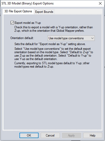
3D File Export Options
Specify the axis orientation to use in the export. Global Mapper labels the vertical axis as Z, but in some 3D formats the vertical axis is designed as the Y-axis. Check the Export model as Y-up option to use the Y-up axis orientation.
Export Bounds
3D Mesh features do not support cropping within mesh objects. With a specified export bounds, mesh features inside the export bounds will be exported, uncropped. Mesh features with no part inside the export bound will not be included in the export.
For more information on the bounds specification options see Export Bounds.
Format Updates
Below is a summary of recent changes to STL format support: