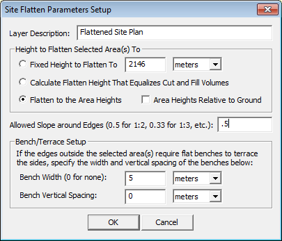
If one or more area features is selected and terrain data is loaded, the Advanced Feature Creation and Analysis/Measurement right-click Digitizer or Selection Mode/3D Viewer submenus will contain the Calculate Flattened Site Plan Grid from Selected Area(s) option. When selected the Setup Site Flatten Parameters dialog (pictured below) appears, allowing you to setup the site flattening operation.

You can specify the height at which you wish to flatten the areas to or
allow a height to automatically be calculated that results in an approximately
equal amount of terrain needing to be cut and filled. This is useful in
estimating real-world build site materials so little or no material will
not to be brought in or hauled out. If the selected areas already contain
elevation values you can also choose to flatten to them, allowing flattening
to non-level surfaces. You can also setup the allowed slope from the site
edges to the terrain surface as well as what width and vertical separation
of benches/terraces to use if required.
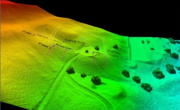
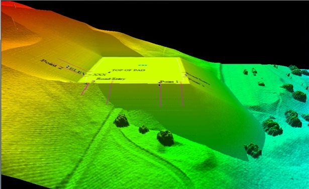
The images below show the 3D viewer before and then after performing a flattening operation on a hillside:


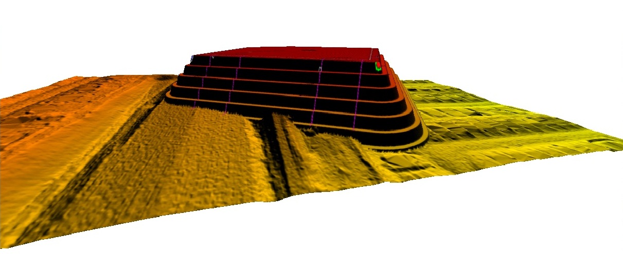
The images below shows the 3D viewer after an operation to flatten a site high above the terrain surface, mainly to illustrate how the terracing works. Note how the new surface matches up with the original terrain surface:
